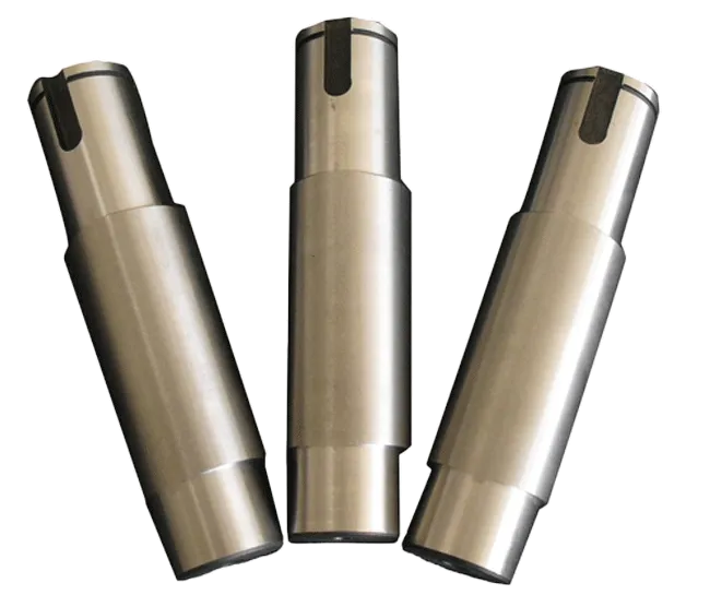
Products Description
An eccentric shaft is a special type of shaft component, characterized by the fact that its geometric center (axis) does not coincide with its rotational center, with a certain eccentricity. This structural design allows it to convert rotational motion into reciprocating motion in mechanical transmission or achieve specific eccentric transmission functions, making it widely used in various mechanical devices.
I. Basic Structure and Core Parameters
- Structural Composition
- Main shaft part: A cylindrical main body matched with components such as bearings, rotating around the rotational center.
- Eccentric part: A shaft segment deviating from the rotational center, where the geometric center of the eccentric part has an eccentricity (e is the distance between the two centers) from the rotational center of the main shaft.
- Shaft neck: A part used for installing transmission components such as gears and pulleys, which may be coaxial with the main shaft or synchronously offset with the eccentric part.
- Core Parameters
- Eccentricity (e): The distance between the rotational center and the geometric center of the eccentric part, which is a key parameter determining the function of the eccentric shaft and directly affects the stroke of reciprocating motion (stroke = 2e).
- Shaft diameter: The diameter of the main shaft and the eccentric part, which needs to be designed according to the bearing capacity.
- Length: The total length of the shaft and the effective length of each segment, adapted to different installation spaces.
- Material: Usually medium carbon steel (such as 45 steel), alloy structural steel (such as 40Cr), etc., which need to be subjected to processes such as quenching and tempering, and surface quenching to improve strength and wear resistance.
II. Working Principle
The operation of the eccentric shaft is based on the principle that "eccentric rotation generates reciprocating displacement": when the shaft rotates uniformly around the rotational center, the geometric center of the eccentric part will move in a circular motion with the rotational center as the center and the eccentricity as the radius, thereby pushing the parts matched with it (such as connecting rods, sliders) to produce reciprocating linear motion or swing.
For example, in an engine, the eccentric shaft can drive the valve lifter to open and close the valve; in a press, the rotational motion of the motor is converted into the up and down stamping motion of the slider through the eccentric shaft.
For example, in an engine, the eccentric shaft can drive the valve lifter to open and close the valve; in a press, the rotational motion of the motor is converted into the up and down stamping motion of the slider through the eccentric shaft.
III. Main Types
According to the structure and purpose, eccentric shafts can be divided into the following categories:
- Single eccentric shaft: With only one eccentric part, suitable for simple reciprocating motion scenarios (such as small compressors).
- Multi-eccentric shaft: Contains multiple eccentric parts, and each eccentric part has different eccentricities or phase angles, which can realize complex multi-action linkage (such as camshafts integrating eccentric structures in textile machinery).
- Stepped eccentric shaft: The diameters of the main shaft and the eccentric part are different, forming a stepped shape, used in equipment that requires graded transmission.
IV. Application Fields
With the characteristic of converting rotational motion into reciprocating motion, eccentric shafts are widely used in:
- Automobile industry: Engine valve mechanism, steering system, oil pump drive.
- General machinery: Transmission mechanisms of presses, crushers, and vibrating screens.
- Textile machinery: Controlling the let-off and take-up actions of looms.
- Machine tool equipment: Power transmission of feed mechanisms and indexing devices.
- Medical equipment: Power components of massage equipment and infusion pumps.
V. Processing Technology
The difficulty in processing eccentric shafts lies in ensuring the positional accuracy between the eccentric part and the main shaft (the eccentricity error needs to be controlled within 0.01~0.05mm). Common processes are as follows:
- Turning processing: Turning the eccentric part by adding gaskets to the three-jaw chuck, using a special eccentric fixture, or positioning with double centers.
- Grinding processing: For eccentric shafts with high precision requirements, the cylindricality and surface roughness of the eccentric part need to be corrected by an external cylindrical grinder.
- Heat treatment: Quenching and tempering to improve the overall strength, and surface quenching to enhance the wear resistance of the shaft neck and eccentric part.
- Inspection: Using tools such as dial indicators and eccentricity meters to measure the eccentricity to ensure it meets the design requirements.
VI. Difference from Crankshaft
Although both eccentric shafts and crankshafts can convert rotational-reciprocating motion, there are obvious differences between them:
| Comparison Item | Eccentric Shaft | Crankshaft |
|---|---|---|
| Structure | Single shaft body + eccentric part, simple structure | Multiple crank throws (including main journal and connecting rod journal), complex structure |
| Function | Mainly used for small-load, short-stroke transmission | Used for large-load, long-stroke transmission (such as engine piston drive) |
| Eccentricity | Fixed and usually small | The crank throw eccentricity is large, adapted to the piston stroke |


